This is a comprehensive guide to the 78L05 pinout, including the popular 78l05 to92 pinout and common 78l05 smd pinout variants like SOIC-8, SOT-23, and SOT-89. You'll find the LM78L05 pinout diagram, pin configuration details, and pin descriptions for this widely used 5V positive 78l05 voltage regulator pinout. We cover the schematic (78l05 pinout circuit), block diagram, and package info from the datasheet. Although the TO-92 package resembles a standard transistor, the LM78L05 is a complete voltage regulator IC; understanding the correct 78l05 regulator pinout is essential for circuit design.
Datasheet primarily used: Texas Instruments LM78Lxx Series (Rev. M). Note that some packages like SOT-89 might be offered by other manufacturers; always verify with the specific datasheet for your part.
1. 78L05 Pinout Diagram
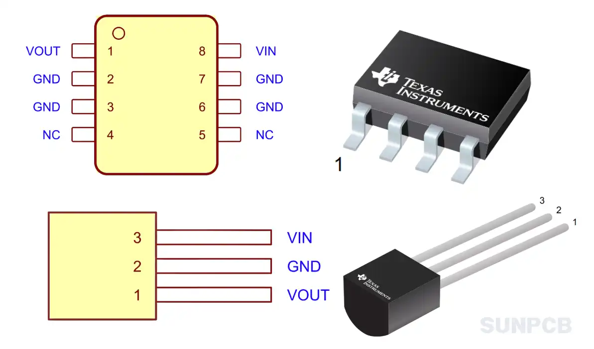
Figure: 78L05 Pinout Diagram Examples (e.g., TO-92 Bottom View, SOIC-8 Top View - See Datasheet Pages 3-4)
This diagram visually represents the LM78L05 pin configuration for various packages.
![]() LM78L05 pinout diagram pdf download (P3-4/P31)
LM78L05 pinout diagram pdf download (P3-4/P31)
2. 78L05 Pin Configuration and Description
The LM78L05 comes in through-hole (like TO-92) and surface-mount (SMD) packages. Below are the pin details for common variants, covering the 78l05 pinout for both types.
2.1 78L05 TO-92 (LP Package) Pinout (Through-Hole)
This is the classic 78l05 to92 pinout configuration.
| Pin # | Pin Name | Type | Pin Description |
|---|---|---|---|
| 1 | OUTPUT | Output | Regulated +5V output voltage. |
| 2 | GND | Ground | Ground reference (0V) for the regulator. |
| 3 | INPUT | Input | Positive unregulated input voltage (typically 7V to 20V). |
Note: Pin numbering for TO-92 is typically viewed from the bottom.
2.2 78L05 SOIC-8 (D Package) SMD Pinout
A common 78l05 smd pinout used for surface mount designs.
In this package, multiple pins are connected internally to the same function (Input, Output, Ground) for better electrical and thermal performance.
| Pin # | Pin Name | Type | Pin Description |
|---|---|---|---|
| 1 | OUTPUT | Output | Output voltage pin |
| 2 | GND | - | Ground |
| 3 | GND | - | Ground |
| 4 | NC | - | No connection |
| 5 | NC | - | No connection |
| 6 | GND | - | Ground |
| 7 | GND | - | Ground |
| 8 | INPUT | Input | Input supply voltage pin |
2.3 78L05 SOT-23 (DBZ Package) SMD Pinout
A very small 78l05 sot pinout for space-constrained applications.
| Pin # | Pin Name | Type | Pin Description |
|---|---|---|---|
| 1 | OUT | Output | Regulated +5V output voltage. |
| 2 | GND | Ground | Ground reference (0V) for the regulator. |
| 3 | IN | Input | Positive unregulated input voltage (typically 7V to 20V). |
2.4 LM78L05 SOT-89 Package SMD Pinout (Common Variant)
The 78l05 sot 89 pinout is another SMD option, often providing better heat dissipation than SOT-23. While not listed in the linked TI datasheet, it's available from other manufacturers.
Important: The pinout below is typical for SOT-89 packages but *always* verify with the specific manufacturer's datasheet for the exact part you are using, as variations exist.
| Pin # | Pin Name | Type | Pin Description |
|---|---|---|---|
| 1 (Center) | GND | Ground | Ground reference (0V). Often connected to the large tab. |
| 2 | INPUT (VIN) | Input | Positive unregulated input voltage. |
| 3 | OUTPUT (VOUT) | Output | Regulated +5V output voltage. |
| Tab | GND | Ground | Large thermal tab, typically connected to Ground for heat dissipation. |
3. 78L05 Typical Application Circuit Diagram
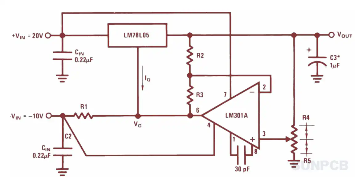
Figure 18: Fixed Output Regulator Schematic (Page 16/34)
Understanding the 78L05 pinout is crucial for correctly implementing this typical 78l05 pinout circuit diagram. This schematic shows the basic setup for the 78l05 voltage regulator pinout.
- An input capacitor ($C_I$, e.g., $0.33 \mu F$) near the INPUT pin stabilizes the input voltage, especially if the power source is distant.
- An output capacitor ($C_O$, e.g., $0.1 \mu F$) near the OUTPUT pin improves stability and transient response.
- Connect the GND pin to the circuit ground.
- Ensure $V_{IN}$ (Pin 3 on TO-92/SOT-23, Pin 2/3 on SOIC-8, Pin 2 on SOT-89) is adequately higher than 5V.
- The regulated 5V is taken from the OUTPUT pin (Pin 1 on TO-92/SOT-23, Pin 1/8 on SOIC-8, Pin 3 on SOT-89).
5. LM78L05 Texas Instruments Overview
5.1 Description
The LM78Lxx series, including the LM78L05, are 3-terminal positive voltage regulators designed for a wide range of applications. These regulators feature internal current limiting and thermal shutdown, making them essentially indestructible. With adequate heat sinking, they can deliver up to 100 mA output current. They are intended as fixed voltage regulators but can be used with external components to obtain adjustable voltages and currents. This LM78L05 pinout guide focuses on the fixed 5V version.
5.2 Overview (From Datasheet)
This series of fixed-voltage integrated-circuit voltage regulators is designed for a wide range of applications. These applications include on-card regulation for elimination of noise and distribution problems associated with single-point regulation. In addition, they can be used with power-pass elements to make high-current voltage regulators. One of these regulators can deliver up to 100 mA of output current. The internal current limiting and thermal shutdown features of these regulators make them essentially immune to overload. When used as a replacement for a Zener diode-resistor combination, an effective improvement in output impedance can be obtained, together with lower bias current.
5.3 Features
- LM78L05 in TO-92 package
- Output Voltage Tolerance specified for $T_J = 25^\circ C$
- Output Current up to 100 mA
- Internal Thermal Overload Protection
- Output Transistor Safe Area Protection
- Internal Short-Circuit Current Limiting
These features make the LM78L05 a robust and easy-to-use regulator for low-power aplications. Note the current limitation (100mA maximum).
5.4 Applications
On-Card Regulation; Single-Point Regulation; High-Current Voltage Regulators (with external pass elements); Zener Diode-Resistor Replacement.
6. LM78L05 Layout Example
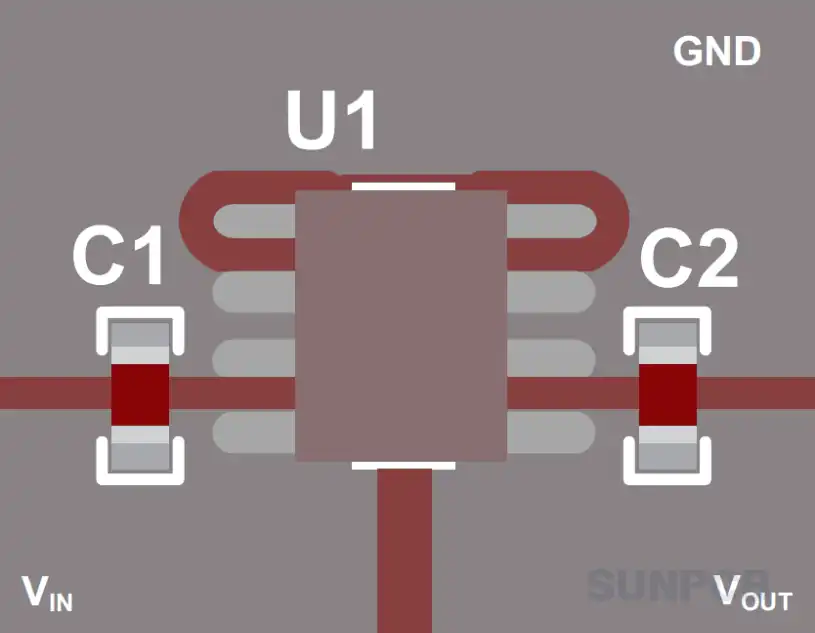
Figure: Layout Example (Page 27/34)
Key layout points from the datasheet examples:
- Place bypass capacitors ($C_I$ and $C_O$) as close as possible to the LM78L05 pins (Input-GND and Output-GND).
- Use a solid ground plane or wide ground traces to minimize impedance and noise. Connect the GND pin directly to this plane.
- Keep the output trace short to minimize voltage drop to the load.
- Ensure input and output traces are adequately sized for the current (though usually not an issue at 100mA max).
- Consider thermal management; for SOIC packages, the multiple GND pins often connect to a larger copper area for heat sinking.
7. LM78L05 Part Numbering System
The datasheet provides ordering information (Device Nomenclature) that helps understand the different variations:
| Part Number Segment | Meaning | Example |
|---|---|---|
| LM78L | Device Family (Positive Linear Regulator, Low Current) | LM78L |
| xx | Output Voltage (05 = 5V, 12 = 12V, etc.) | 05 |
| Suffix (e.g., AC, C) | Grade / Temperature Range (Consult datasheet for specifics, e.g., 'C' often means commercial temp range) | AC or C (check specific part) |
| Package Code | Package Type (LP = TO-92, D = SOIC, DBZ = SOT-23) | LP, D, DBZ |
| Reel/Tape Suffix (e.g., R) | Packaging format for manufacturing (e.g., Tape and Reel) | R (if applicable) |
Example: LM78L05ACLP refers to a 5V output, specific grade (AC), in a TO-92 (LP) package.
8. LM78L05 FAQs and Tips
8.1 FAQs
Q: What is the input voltage range for the LM78L05?
A: Typically 7V to 20V (Absolute Maximum is higher, around 35V, but operating range is lower). Always keep it at least ~2V above the 5V output for proper regulation.
Q: What is the maximum output current of the LM78L05?
A: The maximum rated output current is 100 mA (0.1A). Exceeding this can trigger current limiting or thermal shutdown.
Q: Does the LM78L05 need a heat sink?
A: Usually not for light loads (e.g., < 20-30mA). However, heat generated is $(V_{IN} - V_{OUT}) \times I_{OUT}$. If the input voltage is high and/or the current is near the maximum, it can get hot. Check the power dissipation against the package thermal resistance.
Q: What capacitors are needed with the LM78L05?
A: An input bypass capacitor (e.g., 0.33µF ceramic or tantalum) and an output capacitor (e.g., 0.1µF ceramic or tantalum) are recommended for stability and transient response. Place them close to the IC pins.
Q: What's the difference between LM7805 and LM78L05?
A: The main difference is current capability. LM7805 typically handles up to 1A or 1.5A (package dependent), while LM78L05 is limited to 100mA. The 'L' signifies 'Low Power'.
Q: My LM78L05 output is unstable or oscillating. Why?
A: This is often due to missing or incorrect bypass capacitors, capacitors placed too far from the IC, or excessive load capacitance. Ensure recommended capacitors are used and placed correctly.
Q: Does the LM78L05 require a minimum load current?
A: Technically, it has a quiescent current, but it generally regulates properly even with no external load. Some older datasheets might mention a small minimum load (e.g., 5mA) for tightest regulation, but it's usually not critical for basic operation.
Q: Is the LM78L05 protected against input reverse voltage or output short circuit?
A: It has internal short-circuit (current limiting) and thermal overload protection. It does *not* typically have built-in reverse input voltage protection – applying reversed polarity can damage the IC. A diode in series with the input can provide this protection.
8.2 Usage Tips
- Always use bypass capacitors ($C_{IN}$ and $C_{OUT}$) placed close to the regulator pins for stable operation. Ceramic capacitors are common.
- Ensure the input voltage is always higher than the output voltage plus the dropout voltage (around 1.7V-2V). Check the datasheet for specifics under your load conditions.
- Monitor the power dissipation ($P_D = (V_{IN} - V_{OUT}) \times I_{LOAD} + V_{IN} \times I_Q$). If $P_D$ is high, the device might overheat and trigger thermal shutdown, especially in small packages without heatsinking.
- Double-check the pinout diagram for your specific package (TO-92, SOIC, SOT-23 have different pin arrangements).
- Use a good ground connection. A ground plane is beneficial, especially for surface-mount packages.
- While protected against output shorts, avoid prolonged short circuits as it stresses the component.