Find the MBR2045 pinout diagram, MBR2045 pin configuration, and MBR2045 pin description. This page includes schematics, diagrams, and detailed insights into the MBR2045 Schottky rectifier. Download the datasheet for complete specifications.
1. MBR2045 Pinout Diagram
The MBR2045 pinout diagram illustrates the pin assignments for this Schottky rectifier, essential for circuit design.
2. MBR2045 Pin Configuration and Description
The MBR2045 pin configuration table below details each pin’s function for the TO-220 and TO-220FP packages.
| Pin# | Pin Name | Type | Pinout Description |
|---|---|---|---|
| 1 | Anode 1 | Input | Positive terminal of Diode 1, connects to the input voltage source. |
| 2 | Common Cathode | Output | Common cathode for both diodes, connects to the load or ground. |
| 3 | Anode 2 | Input | Positive terminal of Diode 2, connects to the input voltage source. |
3. MBR2045 Functional Block Diagram
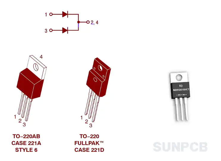
The MBR2045 functional block diagram highlights the internal structure of this dual Schottky rectifier. Key points include:
- Dual Diodes: Two Schottky diodes in a common cathode configuration.
- Low Forward Voltage: Minimizes power loss during rectification.
- High Surge Capacity: Handles high surge currents effectively.
Diagram Location: Page 1
![]() MBR2045 functional block diagram pdf download (P1/P8)
MBR2045 functional block diagram pdf download (P1/P8)
4. MBR2045 ON Semiconductor Overview
4.1 Description
The MBR2045 is a Schottky rectifier designed for high-efficiency power rectification, featuring low forward voltage and high surge capacity.
4.2 Overview
Switch-mode Power Rectifier MBR2045CTG, MBRF2045CTG. Features and Benefits: Low Forward Voltage, Low Power Loss, High Efficiency, High Surge Capacity, 175°C Operating Junction Temperature, 20 A Total (10 A Per Diode Leg).
4.3 Features
- Low Forward Voltage
- Low Power Loss / High Efficiency
- High Surge Capacity
- 175°C Operating Junction Temperature
- 20 A Total (10 A Per Diode Leg)
- Pb-Free and RoHS Compliant
These features ensure reliable performance in high-temperature and high-current applications. Note the Pb-Free compliance for environmental standards.
4.4 Applications
Power Supply - Output Rectification; Power Management; Instrumentation
5. MBR2045 Package Dimension - TO-220-3 / TO-220FP-3
The MBR2045 package dimension diagram provides critical measurements for PCB layout design.
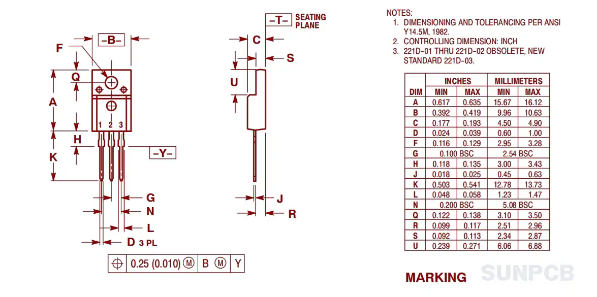
Key points for the package layout:
- Epoxy Case: Molded epoxy meets UL 94, V-0 standards.
- Weight: Approximately 1.9 grams.
- Solderable Leads: Supports soldering up to 260°C for 10 seconds.
6. MBR2045 Part Numbering System
The MBR2045 part numbering system is detailed below for ordering clarity.
| Device Order Number | Package Type | Shipping |
|---|---|---|
| MBR2045CTG | TO-220 (Pb-Free) | 50 Units / Rail |
| MBRF2045CTG | TO-220FP (Pb-Free) | 50 Units / Rail |
7. MBR2045 FAQs and Tips
Common questions and practical tips for using the MBR2045 in your designs.
Q: What is the maximum reverse voltage for MBR2045?
A: The peak repetitive reverse voltage is 45V.
Q: Can MBR2045 handle high surge currents?
A: Yes, it supports a non-repetitive peak surge current of 150A.
Q: What is the operating temperature range?
A: The junction temperature range is -65°C to +175°C.
Q: Is MBR2045 suitable for high-frequency applications?
A: Yes, it operates satisfactorily up to several megahertz.
Q: What packages are available for MBR2045?
A: It comes in TO-220 and TO-220FP packages.
Q: Is MBR2045 Pb-Free?
A: Yes, it is Pb-Free and RoHS compliant.
Q: What is the forward voltage at 20A?
A: Maximum forward voltage is 0.72V at 125°C and 0.84V at 25°C.
Q: Can MBR2045 be used in power supplies?
A: Yes, it’s ideal for output rectification in power supplies.
Tips for engineers:
- Use thermal management to keep junction temperature below 175°C.
- Ensure PCB layout accommodates the TO-220 or TO-220FP footprint.
- Verify surge current ratings for transient conditions.
- Check forward voltage drop for efficiency calculations.
- Confirm RoHS compliance for regulatory requirements.