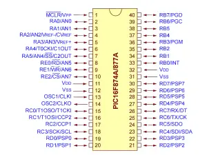
The PIC12C508 is a low-cost 8-bit microcontroller from Microchip. I find its PIC12C508 pinout diagram essential for small projects. The 8-pin DIP package makes the PIC12C508 pin configuration simple to use. Below, I cover key details, include the PIC12C508 pin diagram and more.
1. PIC12C508 Pinout Diagram
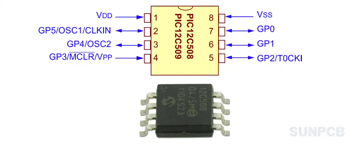
The PIC12C508 pinout diagram shows the 8-pin layout clearly. It’s critical for wiring in microcontrolador PIC12C508 designs.
2. PIC12C508 Pin Configuration and Description
The PIC12C508 pin configuration table lists all 8 pins. Key pins like VDD, VSS, and MCLR are bolded.
| Pin Number | Pin Name | Description |
|---|---|---|
| 1 | VDD | Positive power supply for the device (+5V). |
| 2 | GP5/OSC1/CLKIN | Bidirectional I/O pin. Can also be used as Crystal Oscillator input (OSC1) or External Clock source input (CLKIN). |
| 3 | GP4/OSC2 | Bidirectional I/O pin. Can also be used as Crystal Oscillator output (OSC2). |
| 4 | GP3/MCLR/VPP | Input pin. Master Clear Reset input (MCLR), or Programming Voltage input (VPP). |
| 5 | GP2/T0CKI | Bidirectional I/O pin. Can also be used as external clock input for Timer0 (T0CKI). |
| 6 | GP1/ICSPCLK | Bidirectional I/O pin. Also used as In-Circuit Serial Programming Clock pin (ICSPCLK). |
| 7 | GP0/ICSPDAT | Bidirectional I/O pin. Also used as In-Circuit Serial Programming Data pin (ICSPDAT). |
| 8 | VSS | Ground pin for the device. |
3. PIC12C508 Functional Block Diagram
Based on the architecture overview, key components include:
- RISC CPU: Executes 33 single-cycle instructions.
- Program Memory: 512 x 12 EPROM.
- Data Memory: 25 bytes RAM.
- Timer0: 8-bit real-time clock/counter.
- Oscillator: Internal 4 MHz RC or external options.
4. PIC12C508 Microchip Overview
4.1 Description
The PIC12C508 is a low-cost, 8-bit microcontroller with EPROM and RISC architecture. It’s perfect for simple control tasks.
4.2 Overview
The PIC12C5XX from Microchip Technology is a family of low-cost, high performance, EEPROM/EPROM/ROM-based CMOS microcontrollers. It employs a RISC architecture with only 33 single word/single cycle instructions. All instructions are single cycle (1 μs) except for program branches which have been used. The PIC12C5XX delivers performance an order of magnitude higher than its competitors in the same price category. The 12-bit wide instructions are highly symmetrical resulting in 2:1 code compression over other 8-bit microcontrollers in its class. The easy to use and easy to remember instruction set reduces development time significantly. The PIC12C5XX products are equipped with special features that reduce system cost and power requirements. The Power-On Reset (POR) and Device Reset Timer (DRT) eliminate the need for external reset circuitry. There are four oscillator configurations to choose from, including INTRC internal oscillator mode and the power-saving LP (Low Power) oscillator mode. Power saving SLEEP mode, Watchdog Timer and code protection features also improve system cost, power and reliability.
4.3 Features
- Only 33 single word instructions to learn
- All instructions are single cycle (1 μs) except for program branches which are two-cycle
- Operating speed: DC - 4 MHz clock input DC - 1 μs instruction cycle
- 12-bit wide instructions
- 8-bit wide data path
- Seven special function hardware registers
- Two-level deep hardware stack
- Direct, indirect and relative addressing modes for data and instructions
- Internal 4 MHz RC oscillator with programmable calibration
- In-circuit serial programming
- 8-bit real time clock/counter (TMR0) with 8-bit programmable prescaler
- Power-On Reset (POR)
- Device Reset Timer (DRT)
- Watchdog Timer (WDT) with its own on-chip RC oscillator for reliable operation
- Programmable code-protection
- 1,000,000 erase/write cycle EEPROM data memory
- EEPROM data retention > 40 years
- Power saving SLEEP mode
- Wake-up from SLEEP on pin change
- Internal weak pull-ups on I/O pins
- Internal pull-up on MCLR pin
- Selectable oscillator options: INTRC, EXTRC, XT, LP
- Low power, high speed CMOS EPROM/ROM technology
- Fully static design
- Wide operating voltage range
- Wide temperature range: Commercial, Industrial, Extended
- Low power consumption: < 2 mA @ 5V, 4 MHz, 15 μA typical @ 3V, 32 KHz, < 1 μA typical standby current
These features make the PIC12C508 great for PIC12C508 programming. Watch the oscillator calibration when upgrading to PIC12C508A.
4.4 Applications
Simple control tasks; low-power devices; embedded systems; courtesy beep PIC12C508; roger beep PIC12C508.
5. PIC12C508 Part Numbering System
The PIC12C508 part numbering system for ordering details.
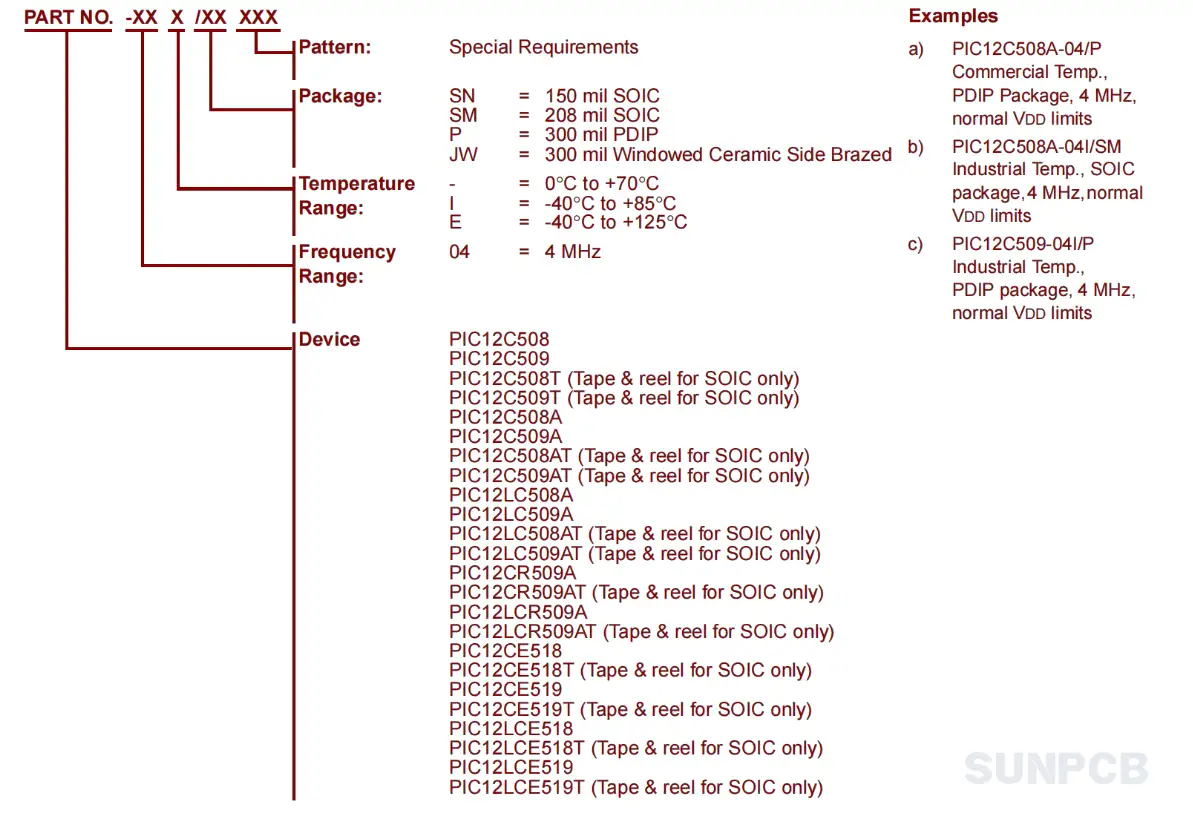
| Parameter | Option | Description |
|---|---|---|
| Device Type | PIC12C508 | 8-bit microcontroller |
| Voltage Range | 2.5-5.5V | Operating voltage |
| Oscillator Calibration | 4 bits | Calibration precision |
| Process Technology | 0.9 μm | Manufacturing process |
6. PIC12C508 FAQs and Tips
FAQs
Q: Can I use a PIC12C508 programmer for this chip?
A: Yes, programmers like PICkit support it. I’ve used one for PIC12C508 programming with no issues.
Q: How do I configure the oscillator?
A: Choose INTRC, EXTRC, XT, or LP. I prefer INTRC for simplicity in small projects.
Q: Is the PIC12C508 same as PIC12F508?
A: No, PIC12C508 vs PIC12F508 differs in memory type. PIC12F508 uses Flash, while PIC12C508 uses EPROM.
Q: Can it drive a courtesy beep PIC12C508 circuit?
A: Yes, its I/O pins can handle simple beeps. I’ve built one for a radio project.
Q: What’s the power consumption in SLEEP mode?
A: It’s < 1 μA typical. I use SLEEP to minmize power in battery designs.
Q: How reliable is the EEPROM?
A: It supports 1,000,000 cycles with > 40 years retention. I’ve never had issues in long-term use.
Q: Can it be used for roger beep PIC12C508?
A: Yes, its Timer0 is great for timing beeps. I programmed one for a CB radio.
Q: Does it support in-circuit programming?
A: Yes, via serial programming. I find it convenient for quick updates.
Tips
- Use a pull-up resistor on MCLR. I’ve seen resets fail without it.
- Enable code protection for production. It saved my IP in a commercial project.
- Calibrate the internal oscillator. I got better timing after tweaking OSCCAL.
- Use SLEEP mode for low power. I cut consumption in a sensor node this way.
- Check voltage range (2.5-5.5V). I encoutered issues at 2V once.
- Add a decoupling capacitor near VDD. It fixed noise in my last design.